")
")
Infrastructure
• System for analysis of the behavior of structures in fatigue tests, Series 1451, K22305 (manufactured by Walter & Bai – Switzerland)
 Figure: 1 System for analysis of the behavior of structures in fatigue tests
Technical specifications:
- 100 kNactuator operating along the two columns forming the frame which can be tilted at various angles, for which the piston stroke is 100 mm (maximum amplitude is ±50 mm) and dynamically frequency is up to max. 35 Hz;
- 63 kN actuator operating horizontally for which the piston stroke is 100 mm(maximum amplitude is ±50 mm) and the dynamic frequency up to max. 35 Hz;
- DION 7 software for static and dynamic tests, multichannel for defining of the cyclic loading tests;
- By using DION 7 software it may define, different kinds of cyclic loadings: sin loading, triangular loading, rectangular loading and so on. For each cyclic loading it may define: the amplitude expressed either in stroke (for example, 5 mm, max. ±50 mm) or maximum load; the frequency (max. 35 Hz); the number of cycles and so on.
The equipment is used for:
- dynamic tests like cyclic fatigue loadings; it may carry out dynamic tests for any mechanical structure or system;
- testing of the specimens made of isotropic materials, wood or advanced materials (composite materials, sandwich structures). The specimens are loaded by applying cyclic loads in bending tests. It can be used to determine Wohler’s curves in cyclic fatigue loadings.
• System for optical analysis of 3D deformations for materials and components, using the digital image correlation (DIC) method
The ARAMIS SRX system (manufactured by ZEISS GOM Metrology) is an optical system containing high-resolution 3D cameras, consisting of hardware and software, which is configured to determine 3D displacements, strains and principal strains, trajectories of points or objects analyzed, using digital image correlation (DIC) technology.
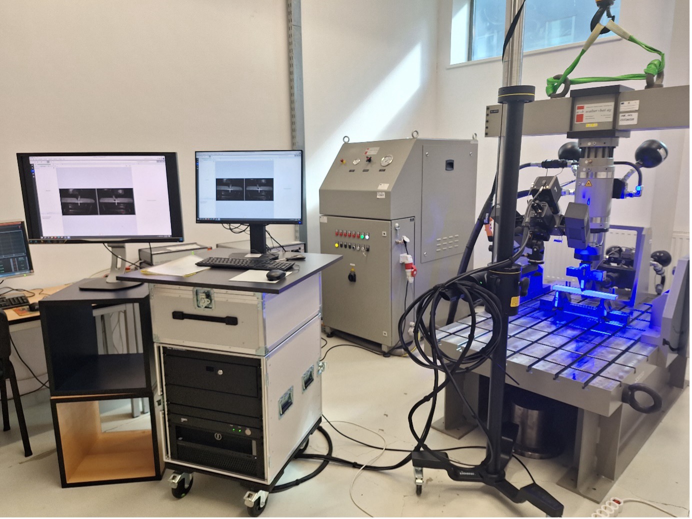
Figure 2: System for optical analysis of 3D deformations for materials and components, using the digital image correlation (DIC) method
Technical specifications:
- contains 2 optical CMOS sensors 2 x 12 Mega Pixels, which provide a resolution of 4096 x 3068 pixels;
- internal memory of the cameras: 8 Gb/ camera;
- image acquisition rate using the internal memory of the cameras is a maximum of 335 Hz at a resolution of 4096 x 3068 pixels (maximum resolution);
- image acquisition rate using a PC, without using the internal memory of the cameras, is a maximum of 75 Hz at a resolution of 4096 x 3068 pixels (maximum resolution);
- MV 400 measurement volume (380 x 290 x 290 mm3);
- LED lighting (blue light technology) of the revolver type;
- laser witnesses for optimal focusing;
- includes the CP40/MV320 artifact with metrological certificate, necessary for calibration;
- lenses with very low distortion, specific to the selected measurement volume, with C-mount configuration;
- electronic controller integrated into the sensor;
- camera positioning stand (height 1.8 m; horizontal sliding arm 0.9 m; sensor mounting station with three-axis manipulation; wheels with locking system);
- PC of type Rack 19” Dell Tower 7820: 2 × Intel Xeon Gold 6136 3.0 GHz (12-Core) processors; 128 GB RAM (2666 MHz); NVIDIA Quadro P4000 8 GB GDDR5 graphics card, OpenGL 4.5, 4 × DisplayPort outputs; 1 TB PCIe SSD; Gigabit LAN interface; dedicated ARAMIS network card of type Dual 10-Gigabit;
- display monitor 1: 24” diagonal (min. resolution 1920 × 1080, integrated audio system) and display monitor 2: 32” diagonal (min. resolution 1920 × 1080, integrated audio system);
- operating system: Windows 10 Pro 64-bit;
- software: GOM Correlate Professional.
This equipment is intended for:
- determining of the distributions of 3D displacements (graphically plotted in the 3D colour map) for the points located on the evaluated surface of the mechanically loaded structure (or part/ specimen);
- determining the field of the normal strains and shear strains (graphically plotted in the 3D color map) for the evaluated surface by calculating the strain tensor on the surface;
- determining the variation of 3D displacements and strains during the mechanical test, for the points of interest located on the evaluated surface;
- determining the movement trajectories for selected elements in the mechanical systems being in motion;
- obtaining measurement reports that can be exported as video sequences (avi/ mpeg), image series (jpg/ png) or PDF pages.
• Integrated system for vibroacoustic analysis (made by LMS GMBH)
This system consists of the following pieces of equipment:
- Data acquisition mobile system for LMS SCADAS vibrations with 4 slots and 8 channels which includes: LMS SCADAS Recorder 5-slot mainframe-SCR05 – 1 item; LMS SCADAS Mobile enhanced 8- channels V/ICP/TEDS input module-SCM-V8-E – 4 items; LMS SCADAS Recorder 16GB compact flash card-SCR-CF16G – 1 item; LMS SCADAS Recorder external compact flash reader-SCR-CFR – 1 item; LMS SCADAS Recorder PDA smart control unit-SCR-PDA – 1 item, and LMS SCADAS Mobile master/slave option-SCM-MS – 1 item;
- Data acquisition mobile system - LMS Scadas with 2 slots x 8 channels for vibrations and 2 slots x 8 channels for tensometry which includes: LMS SCADAS Recorder 5-slot mainframe-SCR05 – 1 item; LMS SCADAS Mobile enhanced 8-canale V/ICP/TEDS input module-SCM-V8-E – 2 items; LMS SCADAS Mobile enhanced 8-canale V/ICP/Bridge input module-SCM-VB8-E – 2 items; LMS SCADAS Mobile master/slave option-SCM-MS – 1 item; one LMS SCADAS Recorder 16GB compact flash card-SCR-CF16G – 1 item; LMS SCADAS Recorder external compact flash reader-SCR-CFR – 1 item, and LMS SCADAS Recorder PDA smart control unit-SCR-PDA – 1 item;
- One PCB -086C03 impact hammer (1 item) that can be used for applying impact loading when analysing mechanical structure vibrations;
- PCB -339A31/NC accelerometers (8 items), PCB 394C06 accelerometer (1 item), and PCB -T333B30 accelerometers (15 items) that are used for the acquisition of acceleration signals in different points of the dynamically loaded mechanical structure (vibrations and impact);
- GRAS microphone with preamplifier with TEDS-46AE (2 items), used for recording sound when testing acoustic insulation panels made of sandwich or composite materials;
- 42AB GRAS calibrator for microphones (1 item);
- Software LMS Test Lab software for vibrations which is used for recording, processing and analyzing the data gathered by means of acquisition boards from accelerometers, force transformer and tensometric marks;
- Software LMS Test Lab software for analysing sustainability data.
The equipment is used for:
- Vibration analysis of mechanical structures, frequency determination;
- Deformation measurement in different points of the structures using the tensometric method;
- Modal analysis of mechanical systems; equipment and machine vibration diagnostic;
- Acoustic analysis and identification of noise sources and spreading.
• Universal testing machine, type LFV 50-HM (Walter & Bai, Switzerland)
- Location: building B, room BS3-b.
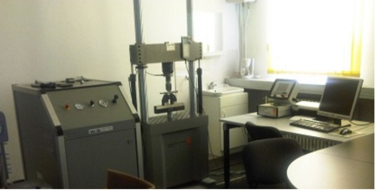
Technical specifications:
- maximum force: 60 kN;
- contains devices for: tensile test, compression test and bending test.
The equipment is used for static mechanical tests (tensile, compression, and bending tests) performed on specimens made of: isotropic materials (steel, aluminum, alloys), wood, foams, composite materials or sandwich-type materials.
• Three-point bending fatigue device for symmetrical alternating load cycles.
Three-point bending fatigue device is compatible only with the mounting system of the universal testing machine of type LFV 50-HM (produced by Walter & Bai, Switzerland), which allows a maximum force of 60 kN (location: building B, room BS3-b).
Technical specifications:
- it includes a support bar having a length of 300 mm, with longitudinal guidance for adjusting the distance between supports;
- two supports (lower supports) for fixing the specimen, frame-type, with top-bottom contact, which allow the mounting of specimens having widths in the range 20–30 mm and thicknesses in the range 5–20 mm;
- central upper head, closed-frame type, with top-bottom contact, for fixing the specimen during variable-load testing, which allows the mounting of specimens having widths in the range 20–30 mm and thicknesses between 5–20 mm;
- three guide roller systems, each roller having a diameter of 10 mm.
The device is used in cyclic fatigue tests of materials.
• MX840 Universal amplifier (data acquisition board)with 8 channels for tensometry
Technical specifications:
- frequency19,2 kHz;
- adapters for 1/4 and 1/2 bridge strain gauges;
- software Catman Easy for data processing, with possibility of creating of the virtual channels to achieve the mathematical calculations real-time for rosette strain gauges.
The equipment is used for measuring of the strains developed at different points of the structures by using the tensometry method. The equipment can be connected to displacement transducers or force transducers for the measurement of uniaxial displacements and forces, respectively.
• Displacement transducer for measuring displacements on the specimen, type 1-WA/100 mm-T
Technical specifications:
- measurement range: 0–100 mm;
- linear deviation: maximum 0.2 %;
- sensitivity: 80 mV/V ± 1 %;
- operating temperature range: –20 to +80 °C;
- connector of type D-SubHD 15, with 15-pin.
The equipment is connected to the MX840 universal amplifier (data acquisition board) and is used to measure uniaxial displacement on the specimen in the range of 0–100 mm.
• Displacement transducer for measuring displacements on the specimen, type 1-WA/10 mm-T
Technical specifications:
- measurement range: 0–10 mm;
- linear deviation: maximum 0.2 %;
- sensitivity: 80 mV/V ± 1 %;
- operating temperature range: –20 to +80 °C;
- connector of type D-SubHD 15, with 15-pin.
The equipment is connected to the MX840 universal amplifier (data acquisition board) and is used to measure uniaxial displacement on the specimen in the range of 0–10 mm.
• Data acquisition platform with 15 channels
The 15-channel data acquisition platform consists of the acquisition board and sensors dedicated for measuring accelerations and angular velocities, for measuring the dynamic performance of vehicles. The platform is shock-resistant, and this can also be used in impact tests.
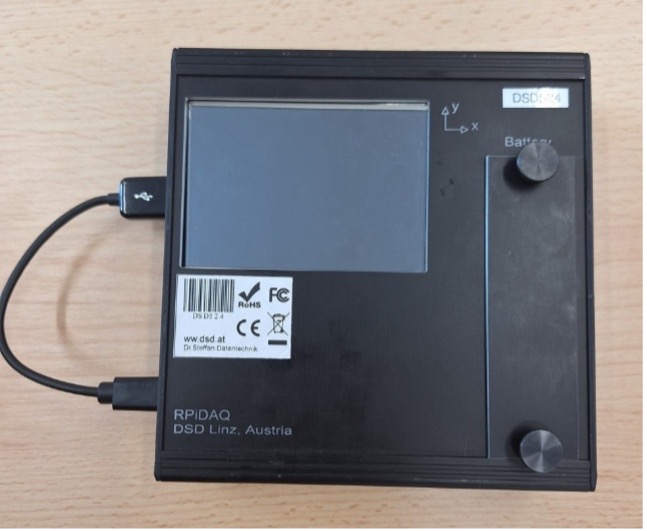
Data acquisition platform with 15 channels
Technical specifications:
- 15 analog input channels (12-bit resolution);
- 4 digital inputs;
- two 3-axial accelerometers (±16g and ±200 g) for impact, crash tests and braking/vehicle dynamics tests, one 3- axial gyroscope (±300 deg/s for roll, pitch and yaw).
- data acquisition frequency: up to 1 kHz per channel;
- data acquisition duration: minimum 300 seconds at the maximum frequency of 1 kHz;
- 3.5” touch-screen display;
- 4 USB ports (two of which are USB 3.0);
- capability to connect a GPS receiver (which is not included);
- dimensions/ weight: 135 mm × 130 mm × 40 mm / 560 g.
The equipment is used for measuring accelerations and angular velocities, for measuring the dynamic performance of vehicles, or in impact/ crash tests.
• Acoustic tube manufactured by Brüel&Kjær (location: building B, room BS2)
The acoustic tube has the following technical characteristics: impedance tube of type 4206; software of type 7758 for data processing and acquisition in case of materials testing.
Equipment is used for determination of the acoustic characteristics of the materials (steel, aluminum, wood, fiber reinforced composite materials, foams, sandwich materials, lignocellulosic composite materials and so on).
• Stereomicroscope SMZ18 (produced by Nikon Corporation)
Technical specifications:
- magnification range from 0.75x to 13.5x allows 11 magnification steps, namely: 0.75/ 1/ 2 /3 /4 /5 /6 /8 /10 /12 /13.5;
- it is equipped with 30x magnification eyepieces and a P2-SHR Plan Apo objective with 1x magnification (0.15 mm numerical aperture), to achieve a maximum magnification of 405x;
- working distance: 60 mm;
- it is equipped with a trinocular tube with a port for mounting a digital camera;
- the trinocular tube has a 0-30° inclination angle with the possibility of adjusting the interpupillary distance;
- it is equipped with a glass turntable stand, which incorporates the LED diascopic lighting system, which is adjustable;
- it is equipped with a ring-type LED source for episcopic lighting;
- high-resolution digital camera, model Nikon DS Ri2 (serial number: 700553) for image acquisition and processing, with the following characteristics: max. resolution 16.25Mp; image resolution 4908x3264 dpi; CMOS image sensor;
- software: NIS ELEMENTS D.
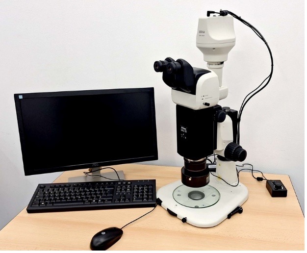
Figure 5: Stereomicroscope SMZ18
The equipment is used for:
- surface examination of specimens or components under bright-field illumination;
- microscopic analysis of failure areas of the specimens made of different materials or of the pieces (it may observe fiber breakage, delaminations at the fiber-matrix interface, delaminations of layers, degradations);
- measurement of the microscopic dimensions on specimen surfaces.
• High-speed image acquisition system (including lens)
The OV301 oven is used for the heat treatment and post-treatment of composite laminates, prepregs and structures made by molding.
High-speed image acquisition system consists in the camera Fastcam Mini AX100 of type 540 (manufactured by PHOTRON) and Lens of type 24-105mm F4 DG OS HSM (manufactured by SIGMA).
Technical specifications of Fastcam Mini AX100 Type 540:
- optical sensor characteristics: color CMOS, 36 bit; minimum resolution 1024 x 1024 pixels at 4000 fps;
- image acquisition frequency: 4,000 frames per second, at maximum resolution, 1024 x 1024 pixels; 540,000 frames per second, at resolution of 128 x 16 pixels;
- internal memory: 16 GB;
- dimensions: 125 mm x 125 mm x 100 mm;
- data transfer interface to PC: Gigabit Ethernet (1000BASE-T);
- CAT-6 Gigabit Ethernet cable - length 5 m;
- software: Photron FASTCAM.
Technical specifications of Lens of type 24-105mm F4 DG OS HSM (manufactured by SIGMA):
- F-type mount;
- focal length: min. 24 mm and max. 105 mm;
- aperture: min. f/22 and max. f/4; focusing distance: min. 0.45 m.
The equipment is used for video recording at a high frame acquisition rate, of short-duration events, dynamic loadings (impact, shock, crash), or bodies motion.
• Oven OV301 (produced by Easy Composites Ltd, by division ECP Industrial, UK)for the thermal treatment of composite materials, with integrated vacuum connections
The OV301 oven is used for the heat treatment and post-treatment of the composite laminates, prepregs and structures made by molding. The maximum temperature of the heat treatment is 200 °C. Internal dimensions: 1070 mm × 475 mm × 500 mm. The oven includes a vacuum system.
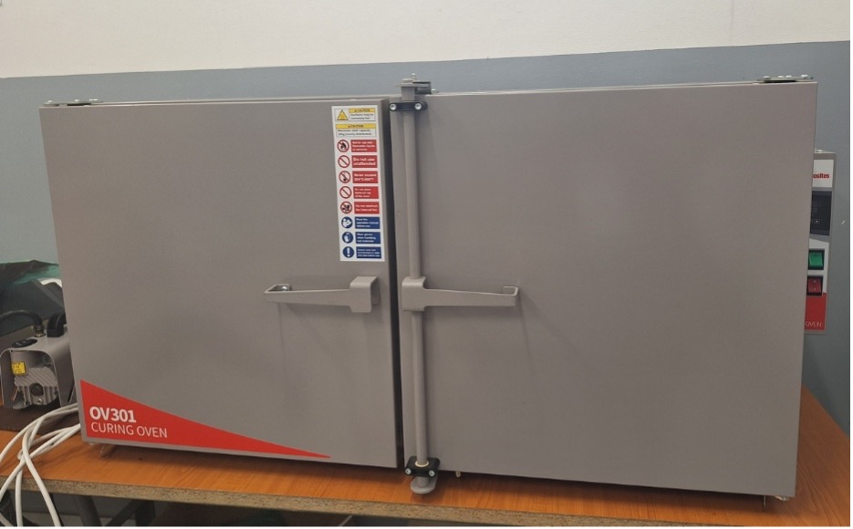
Figure 6: Oven OV301 for the thermal treatment of composite materials, with integrated vacuum connections
• KD2 Pro analyzer for determining the thermal properties of liquids and solids (location: building H)
This equipment is used for determination of the following properties: thermal conductivity; specific heat; thermal diffusivity.; thermal resistivity.
• Rotational viscometer, type ROTAVISC LO-VI S000 (manufactured by IKA)
Technical specifications:
- basic volume of the container: 600 ml;
- viscosity measurement range: 1 – 6000000 mPas;
- working temperature range -100to 300 °C;
- viscosity accuracy: 1 %;
- repeatability: 0.2 %;
- torque: 0.0673 mN·m;
- permissible density: max. 9999 kg/dm3;
- motor power: 4.8 W;
- overload protection;
- speed range 0.01 – 200 rpm;
- time setting range 0.017 - 6000 min.
The equipment is used for determination of the viscosity of liquids with high measurement accuracy.
• Digital viscometer BrookfieldDV-II+ PRO (location: building H)
The equipment is used to measure the fluid viscosity and viscous shear stress.
• Tensiometer SIGMA 700 (location: building H)
This equipment is used for determination of the following properties: surface and interfacial tension; hygroscopicity of powders; dynamic contact angles; critical micellar concentration; density; sedimentation.
• Two low-speed wind tunnels
Technical specifications:
- The smaller tunnel has an open test section of 0.32 m x 0.23 m x 0.85 m and a maximum speed of 35 m/s. It has a digital data acquisition system.
- The larger tunnel has a closed test section of 1.2 m x 0.6 m x 1.2 m, maximum velocity of 40 m/s and turbulence lower than 0.5 pct.
• External aerodynamic balance and accessories, platform type, with software for data acquisition and processing, and with digital control of the measurement system modules
External aerodynamic balance is of the type AFI600T (produced by TecQuipment, UK), serial number TQ405762-001. It works together with the wind tunnel having a test chamber of 1.2m x 0.6 m x 1.2 m (location: building H, room H-I-35).
Technical specifications:
-
- aerodynamic force measurement, with minimum display resolution of 0.01, for: drag force (Fx) within the range [0, 100] N, lift force (Fz) within the range [0, 250] N and pitching moment (My) within the range (-6, +6) N·m;
- digital adjustment and control module for the angular position of the tested model within the range [0°, 360°];
- module for velocity field in a plane: with digital control of the probe position on a depth of 600 mm and a length of 400 mm;
- module for velocity profiles with digital control of the probe position over a length of 300 mm.
- module for flow visualization.
• Anycubic i3 Mega X Printer (manufactured by Shenzhen Creality 3D Technology Co., Ltd., Shenzhen, China)
Technical specifications:
- printing volume: 300 mm × 300 mm × 305 mm;
- layer resolution: 0.05 – 0.3 mm;
- extruder type: single;
- nozzle diameter: 0.4 mm;
- maximum extruder temperature: 250 °C;
- maximum heated bed temperature: 90 °C;
- printing chamber: open;
- connectivity, file input: SD card, USB;
- filament diameter: 1.75 mm;
- supported materials: ABS, PLA etc.;
- operating systems: Windows, Mac OS X, Linux.
The printer is used for rapid prototyping by 3D printing parts or test specimens from PLA or ABS filaments.
• 3D Creality Ender 3 Printer (manufactured by Shenzhen Creality 3D Technology Co., Ltd., Shenzhen, China)
Technical specifications:
- precision: ± 0.1 mm;
- filament diameter: 1.75 mm;
- compatible filament types: PLA, TPU, copper, wood;
- nozzle temperature: 250 °C;
- supported file formats: STL, OBJ, AMF;
- printing area dimensions: 220 mm × 220 mm × 250 mm;
- connectivity, file input: USB / TF card;
- compatible slicing software: Creality Slicer, Cura, Repetier-Host, Simplify 3D;
- power consumption: 270 W.
The printer is used for rapid prototyping by 3D printing parts or test specimens from PLA or ABS filaments.
• Nikon D3500 Camera, 24.2 MP, black + AF-P 18-55 mm VR Lens
Technical specifications:
- lens: AF-P 18-55 mm VR;
- sensor resolution: 24.2 MP
- image resolution: 6000 × 4000; 4496 × 3000; 2992 × 2000;
- video resolution: HD, Full HD;
- video format resolution: 1920 × 1080; 1280 × 720.
• Linear displacement sensor, type OPKON RTL 275 D 5K
The digital oscilloscope is of the type MP720011 (produced by Multicomp PRO, UK).
Technical specifications:
- bandwidth: 100 MHz;
- sample rate: 1 GS/s;
- Horizontal Scale (s/div): 2ns/div - 1000s/div, step by 1 - 2 – 5;
- channels: 2;
- display: 7″colour LCD, 800 × 480 pixel;
- input impedance: 1MΩ±2%, in parallel with 20pF ±5pF;
- channel isolation: 50Hz : 100 : 1, 10MHz : 40 : 1;
- max. input voltage: 400V (PK - PK) (DC+AC, PK - PK);
- DC gain accuracy: ±3%;
- record length: 10K.
The equipment allows digital display of the waveform and measurement of an electrical signal.
• Thermal camera, type FLIR TG267 (produced by FLIR Systems (Wilsonville, Oregon, SUA)
Technical specifications for measurement:
- temperature range: -25 ... +380 ºC;
- accuracy: ±3 ºC within the range -20 ºC ... +50 ºC;
- accuracy: ±1.5 ºC within the range +50 ºC ... +100 ºC;
- accuracy: ±2.5 ºC within the range +100 ºC ... +380 ºC;
- response time: 150 ms;
- display resolution: 0.1 ºC;
- spotmeter;
- digital camera resolution: 2 MP (1600 × 1200 pixels).
Technical specifications for image/ display:
- field of view (FOV): 57º × 44 º;
- minimum focusing distance: 0.3 m;
- thermal sensitivity (NETD): < 0.070 ºC (70 mK);
- frame rate: 8.7 Hz;
- screen size: 2.4”, color;
- display resolution: 320 × 240 pixels.
The equipment is used for:
- Thermal camera FLIR TG267 allows displaying the temperature and thermal image for the surface of the scanned object.
- It can be used to identify hot spots and thermal bridges for the scanned object. Thermal images along with the measured temperature value can be saved.